
- NETWORK TOPOLOGY DIAGRAM SERIAL
- NETWORK TOPOLOGY DIAGRAM UPDATE
- NETWORK TOPOLOGY DIAGRAM PROFESSIONAL
- NETWORK TOPOLOGY DIAGRAM SERIES
Top of Page Automatically link external data to network shapes Repeat these steps for each shape you want to link to data. When you run the Automatic Link wizard, you can specify which column in the data source matches which field in the shape data.

In the Shape Data window, type an asset number or other unique identifier from the data source into the appropriate field. Right-click a network shape in your drawing, point to Data on the shortcut menu, and then click Shape Data. A network topology diagram helps visualize the communicating devices. For example, if you add an asset number to each shape and you have a column for asset numbers in your data source, Visio can use that number to match the rows in the table to corresponding shapes in the diagram. The ideal network topology depends on each businesss size, scale, goals, and budget. Top of Page Add initial data to identify the equipment shapesīefore you can automatically link imported data to your network shapes, you need to add information to your shapes to uniquely identify each one. It represents the components of a network and how those components work together to create an efficient computer network.
NETWORK TOPOLOGY DIAGRAM UPDATE
However, you cannot update your data source by changing the data in your drawing. A network diagram is a visual representation of a complex computer network. This data can be refreshed when the data in the data source changes. Note: The data that appears in the External Data window is a snapshot of your source data at the time of the import. When the device shape is correctly connected to the Ring network or Ethernet shape, the connection point turns red, indicating that it is glued. When the pointer changes to a four-headed arrow, drag it to a connection point on one of the device shapes. Import external data about equipment into your drawingĪdd initial data to identify the equipment shapesĪutomatically link external data to network shapesĬlick New, and then under Template Categories, click Network.įrom Network and Peripherals, drag a Ring network or Ethernet shape onto the drawing page.įrom Computers and Monitors or Network and Peripherals, drag device shapes onto the drawing page.Īttach devices to the Ring network or Ethernet shape by using the shape's built-in connectors:Ĭlick the Ring network or Ethernet shape.
NETWORK TOPOLOGY DIAGRAM PROFESSIONAL
NETWORK TOPOLOGY DIAGRAM SERIAL
■ A Z-shaped line represents a serial link.Ĭontinue reading here: Extended Star Topology ■ A straight line represents an Ethernet link. ■ A laptop or computer and monitor represent an end user PC. ■ A rectangular box with arrows represents a workgroup switch. ■ A cylinder with arrows represents a router. ■ A cloud represents the Internet or WAN connection. Figure 1-3 shows a typical network diagram.
NETWORK TOPOLOGY DIAGRAM SERIES
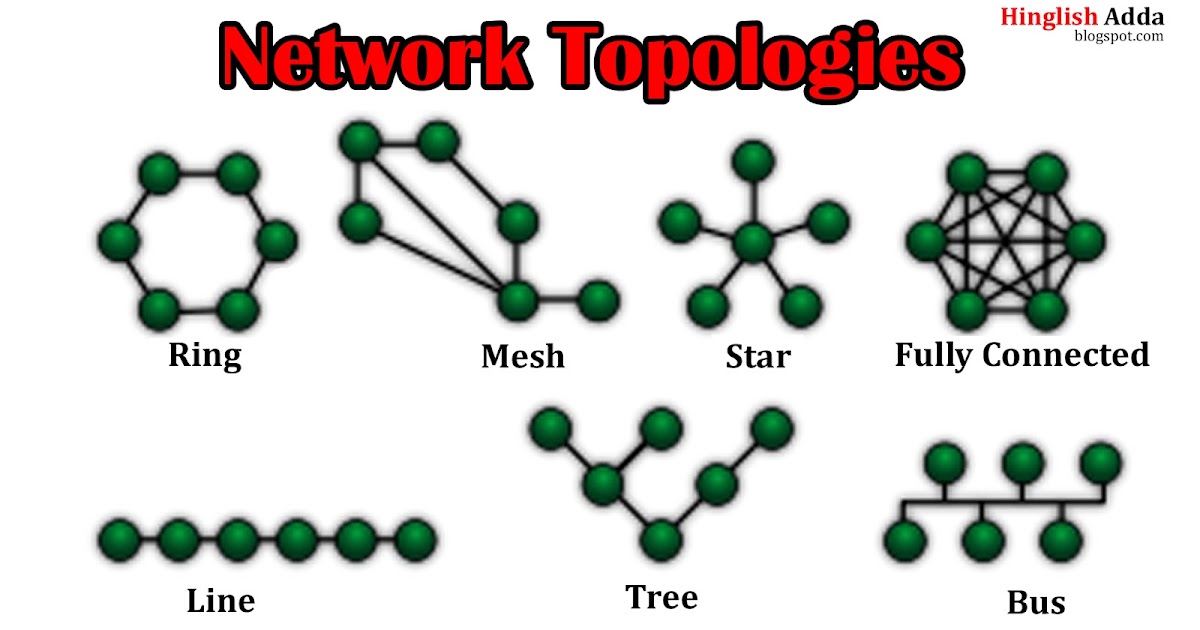
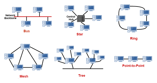
The network topology is commonly represented by a series of lines and icons. The amount of information and the details of that information differ from organization to organization. The network diagram uses common symbols to capture information related to the network for planning, reference, and troubleshooting purposes. When designing and describing a computer network, you use a drawing or diagram to describe the physical components and how they are interconnected.


 0 kommentar(er)
